Products
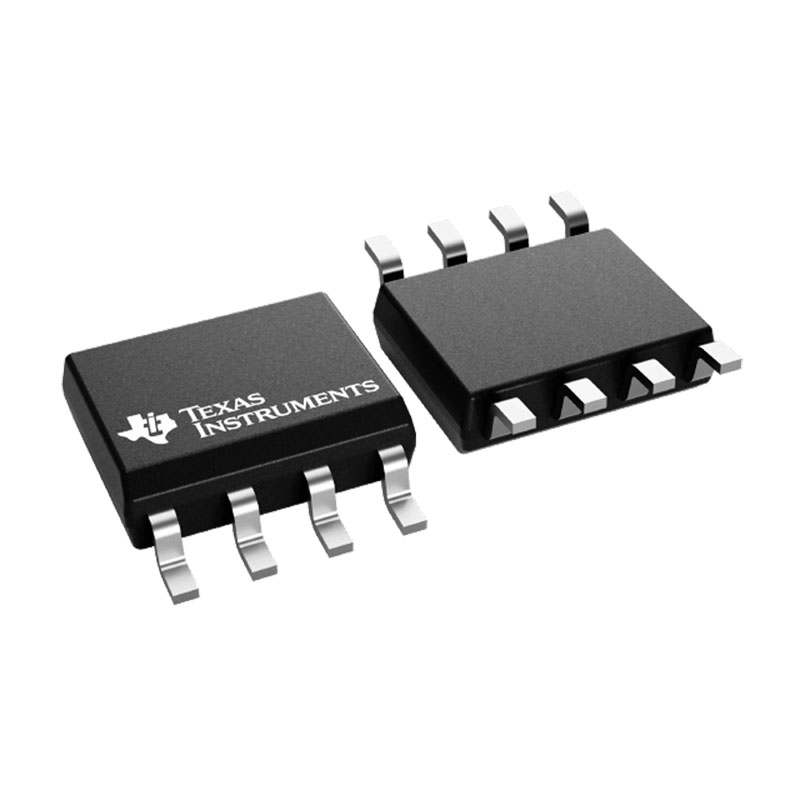
SN65HVD251DR High Speed CAN Transceiver with Short Loop Delay
Features for the SN65HVD251
●Drop-In Improved Replacement for the
PCA82C250 and PCA82C251
●Bus-Fault Protection of ±36 V
●Meets or Exceeds ISO 11898
●Signaling Rates(1) up to 1 Mbps
●High Input Impedance Allows up to 120 Nodes
on a Bus
●Bus Pin ESD Protection Exceeds 14 kV HBM
●Unpowered Node Does Not Disturb the Bus
●Low-Current Standby Mode: 200-µA Typical
●Thermal Shutdown Protection
●Glitch-Free Power-Up and Power-Down CAN Bus
●Protection for Hot-Plugging
●DeviceNet Vendor ID #806
●APPLICATIONS
○CAN Data Buses
○Industrial Automation
○SAE J1939 Standard Data Bus Interface
○NMEA 2000 Standard Data Bus Interface
(1) The signaling rate of a line is the number of voltage transitions that are made per second expressed in bps (bits per second).
All other trademarks are the property of their respective owners
Description for the SN65HVD251
The HVD251 is intended for use in applications employing the Controller Area Network (CAN) serial communication physical layer in accordance with the ISO 11898 Standard. The HVD251 provides differential transmit capability to the bus and differential receive capability to a CAN controller at speeds up to 1 megabits per second (Mbps).
Designed for operation in harsh environments, the device features cross-wire, overvoltage and loss of ground protection to ±36 V. Also featured are overtemperature protection as well as –7-V to 12-V common-mode range, and tolerance to transients of ±200 V. The transceiver interfaces the single-ended CAN controller with the differential CAN bus found in industrial, building automation, and automotive applications.
Rs, pin 8, selects one of three different modes of operation: high-speed, slope control, or low-power mode. The high-speed mode of operation is selected by connecting pin 8 to ground, allowing the transmitter output transistors to switch as fast as possible with no limitation on the rise and fall slope. The rise and fall slope can be adjusted by connecting a resistor to ground at pin 8; the slope is proportional to the pin’s output current. Slope control with an external resistor value of 10 kΩ gives about 15-V / µs slew rate; 100 kΩ gives about 2-V/µs slew rate.
If a high logic level is applied to the Rs pin 8, the device enters a low-current standby mode where the driver is switched off and the receiver remains active. The local protocol controller returns the device to the normal mode when it transmits to the bus.
1. Who are the staff in your R & D department? What are your qualifications?
-R & D Director: formulate the company’s long-term R & D plan and grasp the direction of research and development; Guide and supervise r&d department to implement company r&d strategy and annual R&D plan; Control the progress of product development and adjust the plan; Set up excellent product research and development team, audit and training related technical personnel.
R & D Manager: make new product R & D plan and demonstrate the feasibility of the plan; Supervise and manage the progress and quality of r&d work; Research new product development and propose effective solutions according to customer requirements in different fields
R&d staff: collect and sort out key data; Computer programming; Conducting experiments, tests and analyses; Prepare materials and equipment for experiments, tests and analyses; Record measurement data, make calculations and prepare charts; Conduct statistical surveys
2. What is your product research and development idea?
- Product conception and selection product concept and evaluation product definition and project plan design and development product testing and validation launch to market


